
Effluent Stripper Column for Methanol and Solvent Recovery
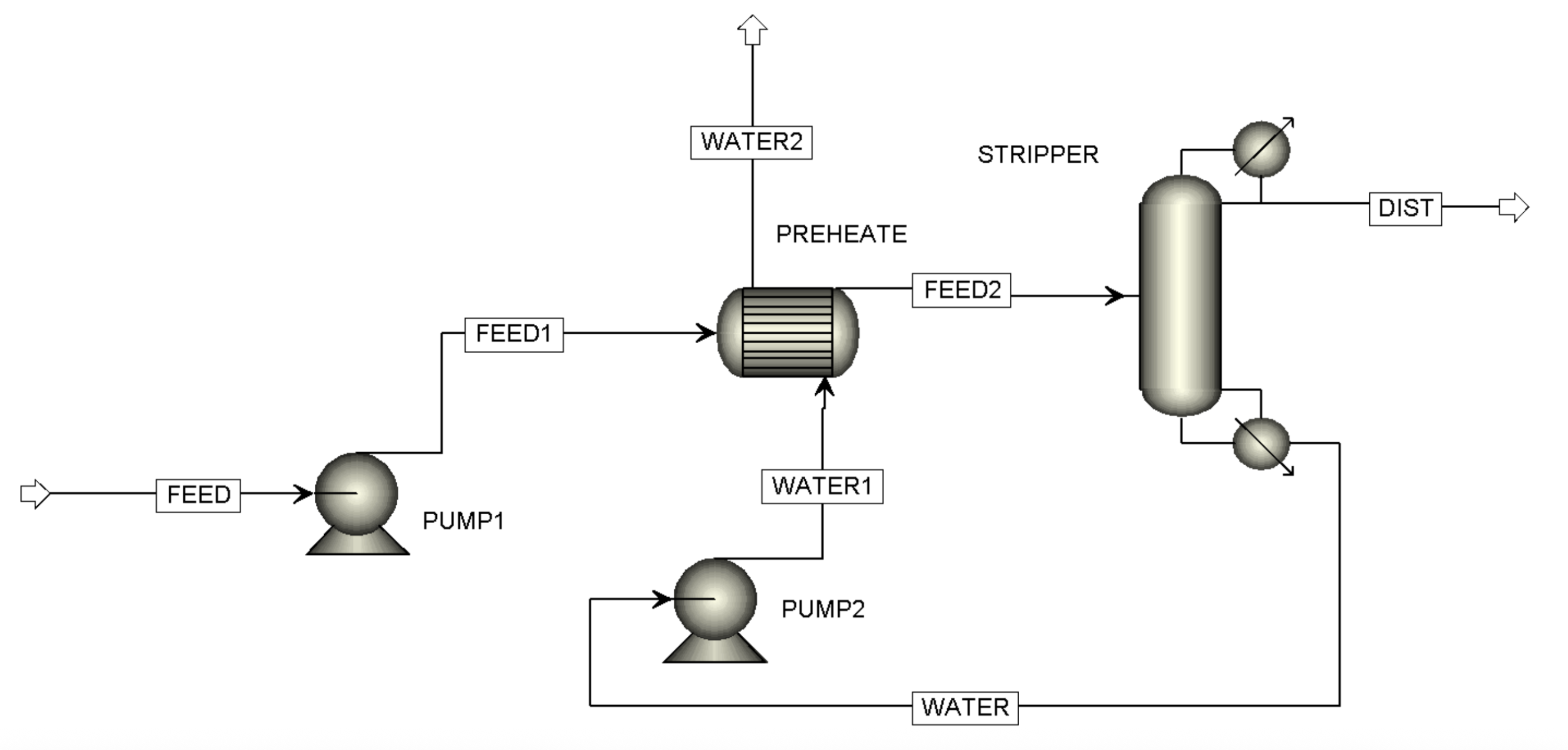
Effluent Stripper Column for Methanol Solvent Recovery
The stripper column receives effluent containing methanol, water, and dissolved solids. This effluent is preheated before entering the column. Inside the stripper, heat is applied so that the methanol present in the effluent is volatilized.
The methanol-rich vapor exits from the overhead of the column, where it is condensed and collected as recovered methanol for reuse. The remaining portion of the effluent flows down to the bottom of the stripper, leaving as a stream of mostly clean water with dissolved salts and only a trace of methanol.
We carry out heat integration so that total steam consumption is low, and we select proper packing or trays — or a combination of both — to ensure a top solvent concentration of more than 80% and a very minimum COD at the bottom.
Thus, the process ensures that methanol is recovered from the effluent, while producing a treated effluent stream suitable for disposal or further treatment. Our expertise is demonstrated in our 100 KLPD stripper column project.
Summary
Solvent Recovery: Methanol is volatilized, condensed overhead and recovered for reuse — targeting a top solvent concentration above 80%.
Heat Integration: Heat integration across the process keeps total steam consumption low, reducing operating cost.
Treated Effluent: A bottom stream of mostly clean water with minimum COD, suitable for disposal or further treatment.
Mass Balance
Scroll horizontally to see all streams →
| Material | ||||||||
|---|---|---|---|---|---|---|---|---|
| Stream Name | Units | FEED | FEED1 | FEED2 | DIST | WATER | WATER1 | WATER2 |
| MIXED Substream | ||||||||
| Phase | Liquid Phase | Liquid Phase | Liquid Phase | Liquid Phase | Liquid Phase | Liquid Phase | Liquid Phase | |
| Temperature | C | 30 | 30.09 | 62 | 73.73 | 100.54 | 100.69 | 56.21 |
| Pressure | bar | 1.1 | 2 | 2 | 1.00 | 1.03 | 3.00 | 3.00 |
| Mass Density | kg/cum | 945.29 | 945.21 | 915.56 | 761.36 | 971.26 | 971.13 | 1008.93 |
| Volume flow rate, mixture | l/hr | 1030.00 | 1030.09 | 1063.44 | 446.57 | 652.39 | 652.49 | 628.04 |
| Mass Flows | kg/hr | 973.65 | 973.65 | 973.65 | 340.00 | 633.65 | 633.65 | 633.65 |
| METHANOL | kg/hr | 292.09 | 292.09 | 292.09 | 290.85 | 1.24 | 1.24 | 1.24 |
| WATER | kg/hr | 652.34 | 652.34 | 652.34 | 49.15 | 603.19 | 603.19 | 603.19 |
| TDS | kg/hr | 29.21 | 29.21 | 29.21 | trace | 29.21 | 29.21 | 29.21 |
| Mass Fractions | ||||||||
| METHANOL | 0.30 | 0.30 | 0.30 | 0.86 | 0.003 | 0.003 | 0.003 | |
| WATER | 0.67 | 0.67 | 0.67 | 0.14 | 0.951 | 0.951 | 0.951 | |
| TDS | 0.03 | 0.03 | 0.03 | trace | 0.046 | 0.046 | 0.046 | |
NOTE : As it is Result from Simulation Software in Practical Result may Vary 5 to 7%.
FAQs
Sieve trays are typically fabricated from sheet metal — commonly stainless steel or other corrosion-resistant alloys selected to suit the process fluid — with a regular pattern of small holes punched or drilled across the active area.
Vapour rising through the perforations contacts the liquid flowing across the tray, creating a froth that promotes mass transfer. The vapour velocity must be high enough to stop liquid weeping through the holes, yet low enough to avoid excessive entrainment and flooding.
Hole sizes typically range from about 3 mm to 12 mm, with the open area generally between 6% and 15% of the active tray area. The exact geometry is set during design to balance capacity, efficiency, and turndown for the specific service.
Still have questions?
Can't find the answer you're looking for? Please chat to our friendly team.