
Ammonia Stripper and Scrubber System
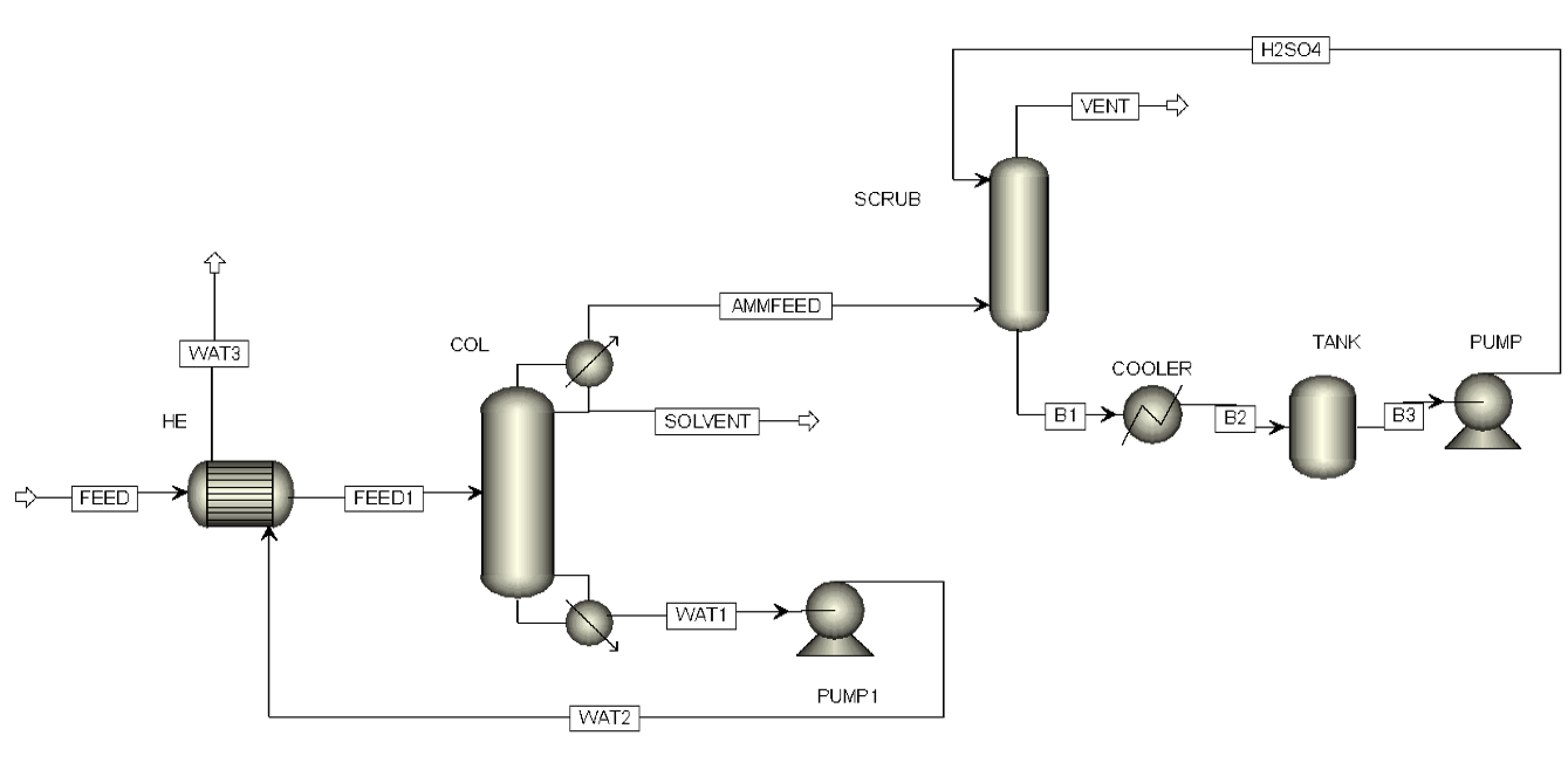
Ammonia Stripper Scrubber System for Wastewater Treatment.
Wastewater containing dissolved ammonia is first introduced into the ammonia stripper column. Inside the stripper, steam is used to heat the bottom and rises counter-current to the wastewater flow. The heat and mass transfer provided by the steam cause the dissolved ammonia to volatilize, separating it from the liquid phase. The treated liquid exits at the bottom of the stripper as a clean water stream with very low residual ammonia (typically <100 ppm).
The ammonia-rich vapor exiting the top of the stripper is then directed to a scrubber column. In this scrubber, the vapor is contacted with a circulating solution of sulfuric acid (H₂SO₄). The ammonia reacts with sulfuric acid according to the reaction:
2NH₃ + H₂SO₄ → (NH₄)₂SO₄
This reaction produces ammonium sulfate, which remains dissolved in the scrubbing liquid. As a result, the scrubber vent gas contains only negligible traces of ammonia.
The scrubber bottom product is an aqueous solution rich in ammonium sulfate, which can be recovered for use as a fertilizer or sent for further processing. Meanwhile, the treated wastewater leaving the stripper bottom is much cleaner and can either be reused in the plant or safely discharged.
Summary
Stripper: Removes ammonia from wastewater using steam.
Scrubber: Captures ammonia from vapor and converts it into ammonium sulfate with H₂SO₄.
Products:
Clean water from stripper bottom
Ammonium sulfate solution from scrubber bottom
Trace-free vent gas
Mass Balance
Scroll horizontally to see all streams →
| Material | ||||||||
|---|---|---|---|---|---|---|---|---|
| Stream Name | Units | FEED | FEED1 | AMMFEED | SOLVENT | WAT1 | WAT2 | WAT3 |
| MIXED Substream | ||||||||
| Phase | Liquid Phase | Liquid Phase | Vapor Phase | Liquid Phase | Liquid Phase | Liquid Phase | Liquid Phase | |
| Temperature | C | 30 | 80 | 60.00 | 95.26 | 100.62 | 100.7 | 50 |
| Pressure | bar | 2 | 2 | 1.01 | 1.01 | 1.03 | 4.0 | 4.0 |
| Mass Density | kg/cum | 997 | 950 | 0.63 | 894 | 931 | 930 | 980 |
| Volume flow rate, mixture | l/hr | 30075.53 | 31594.04 | 119758.10 | 206.56 | 31959.93 | 31964.16 | 30356.26 |
| Mass Flows | kg/hr | 30000.00 | 30000.00 | 75.32 | 184.68 | 29740.00 | 29740.00 | 29740.00 |
| AMMONIA | kg/hr | 90.00 | 90.00 | 62.30 | 24.79 | 2.91 | 2.91 | 2.91 |
| TDS | kg/hr | 300.00 | 300.00 | trace | trace | 300.00 | 300.00 | 300.00 |
| WATER | kg/hr | 29610.00 | 29610.00 | 13.02 | 159.89 | 29437.09 | 29437.09 | 29437.09 |
| Mass Fractions | ||||||||
| AMMONIA | 0.003 | 0.003 | 0.134 | 0.827 | 100 PPM | 100 PPM | 100 PPM | |
| TDS | 0.010 | 0.010 | 0.000 | 0.000 | 0.01 | 0.01 | 0.01 | |
| WATER | 0.987 | 0.987 | 0.866 | 0.173 | 0.99 | 0.99 | 0.99 | |
NOTE : As it is Result from Simulation Software in Practical Result may Vary 5 to 7%.
Scrubber & Ammonium Sulfate Recovery
Scroll horizontally to see all streams →
| Material | ||||||
|---|---|---|---|---|---|---|
| Stream Name | Units | AMMFEED | VENT | Inititial Conc in Tank | Per Hour Conc | After 20 hrs Final Conc |
| MIXED Substream | ||||||
| Temperature | C | 32.00 | 30.00 | 30.00 | 30.00 | 30.00 |
| Pressure | bar | 1.10 | 1.00 | 1.20 | 1.20 | 1.20 |
| Mass Vapor Fraction | 0.99 | 1.00 | 0.00 | 0.00 | 0.00 | |
| Mass Liquid Fraction | 0.01 | 0.00 | 1.00 | 1.00 | 1.00 | |
| Mass Density | gm/cc | 0.00 | 0.00 | 1.01 | 1.01 | 1.01 |
| Mass Flows | kg/hr | 90.00 | 0.02 | 12958.00 | 12958.00 | 14663.44 |
| H2SO4 | kg/hr | 0.00 | 0.00 | 5183.20 | 4924.04 | 259.16 |
| WATER | kg/hr | 0.00 | 0.010 | 7774.80 | 7774.80 | 7774.80 |
| AMMONIA | kg/hr | 90.00 | 0.010 | 0.00 | 0.00 | 0.00 |
| Ammonium Sulfate | kg/hr | 0.00 | 0.00 | 0.00 | 348.92 | 6629.48 |
| Mass Fractions | ||||||
| H2SO4 | 0.00 | 0.00 | 0.40 | 0.38 | 0.02 | |
| WATER | 0.00 | 0.50 | 0.60 | 0.60 | 0.53 | |
| AMMONIA | 1.00 | 0.50 | 0.00 | 0.00 | 0.00 | |
| Ammonium Sulfate | 0.00 | 0.00 | 0.000 | 0.027 | 0.45 | |
NOTE : As it is Result from Simulation Software in Practical Result may Vary 5 to 7%.
FAQs
Sieve trays are typically fabricated from sheet metal — commonly stainless steel or other corrosion-resistant alloys selected to suit the process fluid — with a regular pattern of small holes punched or drilled across the active area.
Vapour rising through the perforations contacts the liquid flowing across the tray, creating a froth that promotes mass transfer. The vapour velocity must be high enough to stop liquid weeping through the holes, yet low enough to avoid excessive entrainment and flooding.
Hole sizes typically range from about 3 mm to 12 mm, with the open area generally between 6% and 15% of the active tray area. The exact geometry is set during design to balance capacity, efficiency, and turndown for the specific service.
Still have questions?
Can't find the answer you're looking for? Please chat to our friendly team.